It’s common knowledge that AUTOSAR was created to standardize the software architecture in automotive systems. The AUTOSAR architecture is based on a 3-layered architecture model, developed jointly by the stakeholders of the automotive industry including – the automobile manufacturers, the suppliers, and the tool developers.
Imagine a car manufacturer, AutoTech, which sources electronic control units (ECUs) from various suppliers. Each supplier uses different software to control similar functions (like engine management, braking systems, or infotainment).
Without AUTOSAR
AutoTech would face challenges in ensuring that all these different software systems work seamlessly together, leading to increased integration and testing efforts.
If AutoTech decides to change a supplier or needs to update software across different ECUs, this would involve significant redevelopment since the software is tightly coupled with the hardware.
Introducing a new feature, like an advanced driver-assistance system, would be complex, as it would require significant coordination and custom integration across various suppliers’ systems.
With AUTOSAR
AutoTech benefits from a standardized software architecture. This means that all suppliers develop software components that conform to a common standard, ensuring compatibility and interoperability.
Software components become hardware independent. If AutoTech switches suppliers or updates an ECU, the impact on the software is minimal, as the new hardware will also comply with AUTOSAR standards.
Introducing new features becomes simpler and more efficient. The modular design allows AutoTech to easily integrate new functions developed by any AUTOSAR-compliant supplier, knowing they will work seamlessly with existing systems.
But how does AUTOSAR achieve this standardization? The AUTOSAR layered architecture is what plays the most significant role here.
AUTOSAR Layered Architecture is the Key to Standardization
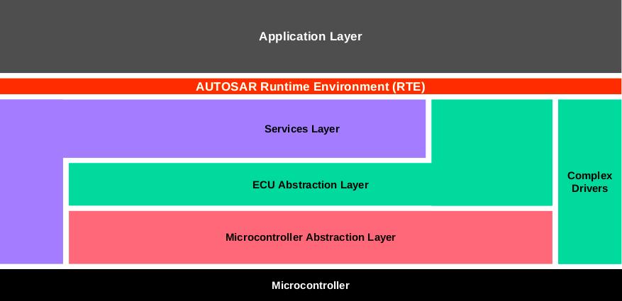
Let us have a quick look at the AUTOSAR architecture. The AUTOSAR specifies a three-layer architecture, which are categorized into following modules:
- Basic software (BSW): can be defined as standardized software module offering various services necessary to run the functional part of the upper software layer. This layer consists of the ECU specific modules along with the generic AUTOSAR modules.It is divided into three sub layers namely the Services layer, ECU (Electronic Control Unit) abstraction layer, and the Microcontroller Abstraction Layer (MCAL).The MCAL is a software module that abstracts all the upper layers ( the application layer and the BSW) Microcontroller. Thus, MCAL helps in making the upper layers independent of the low lying hardware platform.
- Runtime environment (RTE): acts as a middleware between the AUTOSAR application layer and the lower layers. Basically, the RTE layer manages the inter- and intra-ECU communication between application layer components as well as between the BSW and the application layer.
- Application layer: The AUTOSAR application layer includes various application specific software components that are designed to execute specific set of tasks, as per the use-case.
In this blog, we would be discussing about the AUTOSAR Application layer in detail.
The layered AUTOSAR architecture divides software into well-defined layers, each with specific responsibilities, leading to improved maintainability and easier debugging. By abstracting hardware details in lower layers, it enhances portability and scalability of higher-level application software, allowing for greater flexibility and adaptability.
Additionally, this structure facilitates thorough testing and validation of individual layers, significantly enhancing the overall reliability and quality of automotive software.
The Application Layer in AUTOSAR Architecture
The AUTOSAR Application layer constitutes the topmost layer within an AUTOSAR architecture and is identified to be critical for all the vehicle applications. The AUTOSAR standard specifies the application layer implementation using a “component” concept.
While talking about the application layer implementation, three of the most important parts that should be considered are:
- The AUTOSAR application software components
- The AUTOSAR ports of these components
- The AUTOSAR Port Interfaces
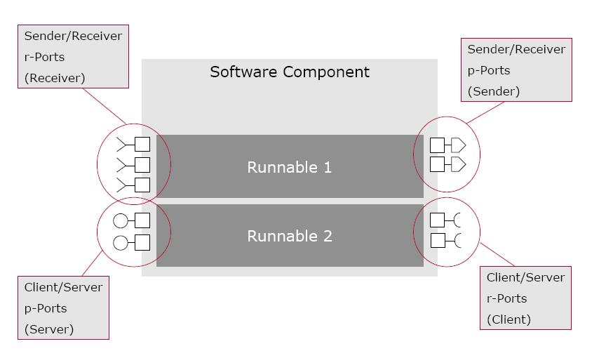
AUTOSAR application software components: A typical E2E(End to End) functionality includes many interconnected AUTOSAR Application Software Components (SW-C). The application software component constitutes the simplest form of an application with certain functionality. AUTOSAR defines standardized interfaces associated with all the application software components required to develop automotive applications.
These software components are connected with the help of well-defined ports. These ports facilitate communication between the software components as well as with the AUTOSAR BSW. In the context of the Application Software Components, there are certain entities called the Runnables, which are basically the procedures that contain the actual implementation of the software components.
Runnable or Runnable Entities are defined within the VFB specifications and is part of an atomic software component (described in a later section). Runnable are defined as the smallest fragments of code or a sequence of instructions given by component and executed by RTE. A runnable entity is triggered either cyclically or during an event such as data reception.
Types of Software Components of AUTOSAR Application Layer:
To understand the AUTOSAR software component in further detail, it is vital to look at the various types in which AUTOSAR SW-Cs are available within the application layer
- Sensor/Actuator Software Component: A type of AUTOSAR Software Component for handling sensor evaluation and actuator control functions. This particular AUTOSAR Software Component depends on the associated sensor/actuator and is independent of the specific ECU, to which it is mapped to.
- Composite Software Component: A composite component offers a logical interconnection of other components, which could be either atomic or composite. These components are called prototypes and usually are not required to be deployed on the same ECU. Instead these can be distributed over several ECUs.
- Application Software Component: The application software component is an atomic software component that implements (a part of) an application. An atomic SW component cannot be decomposed into smaller units and can be assigned to only one ECU.
- Calibration Parameter Component: This component provides values for calibration parameters.
- Service Component: It provides standardized services through standardized interfaces and may interact directly with certain other BSW modules
- ECU-Abstraction Component: It provides access to the ECU’s specific IO capabilities
- Complex Device Driver Component: It generalizes the ECU-abstraction component. It can define ports to interact with other components in specific ways and can also interact directly with other basic-software modules.
- NVBlock Software Component: It allows software components access to non-volatile data.
The AUTOSAR ports: The AUTOSAR Software Components use well-defined ports, which encapsulate certain interfaces as a guarantee for type safety while components are communicating with each other.
A port is mapped to a single component and represents a communication point between the components. This inter-component communication is managed by the Virtual Function Bus (VFB).
The AUTOSAR Interfaces:
As we discussed earlier, the AUTOSAR standard defines certain standardized interfaces for the application software components that are required to develop various automotive applications. This definition of the interfaces helps in obtaining the required functionality of the vehicle application.
In order to better define the communication of data or services through port of a typical component, the AUTOSAR introduced the Interface concept. The port interface required by an application software component serves as the input to the RTE port creation. An AUTOSAR Interface is categorized into:
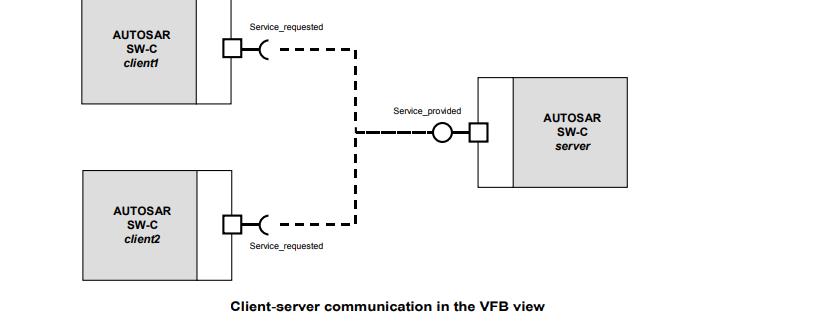
- Client-Server interface: This interface defines a set of operations that can be invoked based on the client-server pattern. Here the client initiates the communication, and requests the server to perform a service.The server performs the request service and sends a response to the request. The direction of the message initiation can be used to identify if the AUTOSAR Software Component is a client or a server. In the diagram below, the client the AUTOSAR SWCs, client 1 and 2 respectively , request a service through the RPorts ( Request Port) which is sent to the, the server AUTOSAR SWC which offers the required services through the PPort ( provider Port).


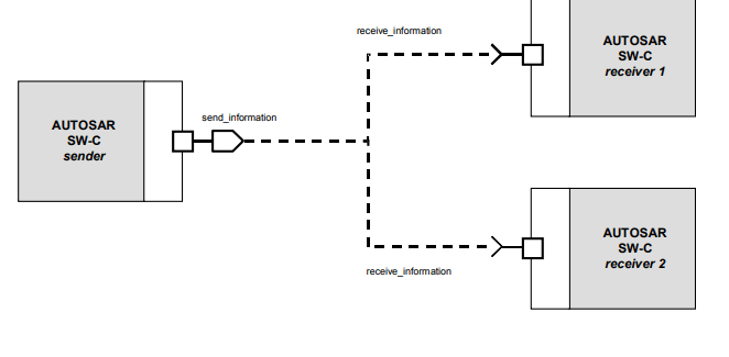
Image: The client server communication between AUTOSAR software components. - Sender-Receiver interface: This interface defines an asynchronous information distribution and allows for a more data-oriented information exchange over the virtual function bus.
- Client-Server interface: This interface defines a set of operations that can be invoked based on the client-server pattern. Here the client initiates the communication, and requests the server to perform a service.The server performs the request service and sends a response to the request. The direction of the message initiation can be used to identify if the AUTOSAR Software Component is a client or a server. In the diagram below, the client the AUTOSAR SWCs, client 1 and 2 respectively , request a service through the RPorts ( Request Port) which is sent to the, the server AUTOSAR SWC which offers the required services through the PPort ( provider Port).
The decision related to what all information should be exchanged through sender-receiver communication and which of the services should be called by the client-server communication – are taken by the interface.
Communication Between the Software Components ( SW-C)
During design time of an AUTOSAR application, the VFB is used to manage the communication between the software components. This virtual bus abstracts the applications from the infrastructure. VFB is an abstract component that is represented usually by the Runtime Environment (RTE) at the runtime, and generated uniquely for each ECU in the AUTOSAR system. The VFB connects the various SWCs in the design model .
The VFB communicates via dedicated ports, which means that the communication interfaces of the application software must be mapped to these ports. The VFB handles communication both within the individual ECU and between ECUs.
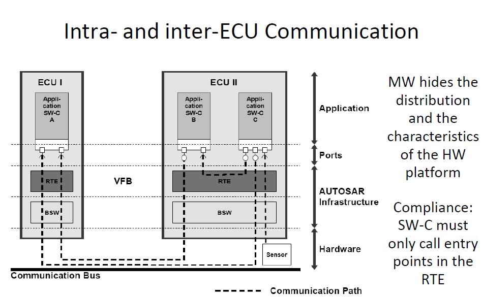
- Inter-ECU. Or
- Intra-ECU
as explained in the diagram above. Both the inter and intra-ECU communication between the application software components communication is managed through the RTE.
The interaction between ECU I and ECU II is an example of inter-ECU communication and takes place through and beneath the RTE and goes via the Basic Software Module. The BSW handles the functions like interactions with the memory, diagnostics, along with communication services ( if needed) for the inter-ECU communication.
The intra-ECU communication, that is the communication within the ECU between the software component B ( SW-C B) and the software component C (SW-C C ) , is entirely through the RTE.As evident from the diagram , the software components that are mapped to a single ECU use the Intra-ECU method.
The Role of RTE: The implementation of the AUTOSAR software components is made independent of available communication mechanisms by the RTE by offering a uniform environment to these to AUTOSAR Software Components ( SWC).
Application layer exchanges data with the underlying layers via the sender and receiver ports of the RTE. Whenever an AUTOSAR software component calls for the service objects, the RTE maps these requests to the actual service object symbols on the local ECU.
The Complex Device Driver Exception – offering direct access to hardware
As the layered nature of the AUTOSAR software architecture does not allow direct access of the hardware by the upper layers, an additional concept was needed to bypass this restriction especially for the resource critical and/or Non-AUTOSAR compliant software components.
And it is here that the Complex Device Driver comes into scenario. The Complex Device Driver basically offers an AUTOSAR Interface to the application layer and thus gains direct access to values on the physical layer.
The concept of Complex driver is useful for application components that call for a direct access to the hardware devices on the ECU. Injection control or electronic valve control applications are good examples of such applications that require direct access to the hardware.
If we look at the AUTOSAR application layer implementation process, it is a function of the AUTOSAR Software Component which is independent of:
- The type of Microcontroller of the ECU being mapped.
- Type of ECU being mapped
- The location of the AUTOSAR Software Component
- The number of times a software component is instantiated within the system or an ECU.
The application software implementation within the AUTOSAR is encapsulated within the software components and forms the core of the AUTOSAR application implementation process.
AUTOSAR Software Components Explained through an Automotive Use-Case
Let’s understand AUTOSAR software components through an example involving an Adaptive Cruise Control (ACC) system in a modern car, and explore how different AUTOSAR software components interact to make this feature work:
- Sensor Actuator Software Component (SASWC)
Role: To interact with sensors and actuators.
A SASWC is responsible for reading data from radar and other sensors that detect the distance and speed of vehicles ahead. It also controls actuators for the braking system and throttle. - Application Software Component (ASWC):
Role: To handle the application logic.
An ASWC takes the sensor data (from SASWC) and processes it to determine the required speed and distance adjustments. It decides when to accelerate, decelerate, or maintain the current speed. - Runnable Entities:
Role: They are the functional units within ASWC.
One runnable entity could be responsible for processing the radar data, another for calculating the required acceleration or deceleration, and another for ensuring that the adjustments adhere to safety parameters. - Client-Server Software Components:
Role: To implement a client-server communication model.
The ACC system (client) might request data from a navigation system (server) to understand upcoming road conditions (like curves or hills) that could affect cruise control adjustments. - NVBlock Software Component:
Role: To manage non-volatile data storage.
This component could be used to store user preferences for ACC, such as preferred following distance or maximum speed settings, ensuring they are retained across engine restarts. - Complex Device Driver (CDD):
Role: To manage complex drivers not standardized in AUTOSAR.
A CDD might be used to interface with a proprietary radar sensor that has specific communication protocols not covered by standard AUTOSAR drivers.
New Meta: Gain detailed insights into AUTOSAR architecture with a focus on its diverse software components. Understand the roles and interactions of key elements within the AUTOSAR layered architecture.
