
In this article, our Automotive Embedded Software development team has helped us understand the layered architecture of ISOBUS protocol software and its application in off-highway vehicle diagnostics.
In order to understand ISOBUS software stack, let’s first learn about the ISO 11783 automotive standard.
What is ISO 11783 Standard?
ISO 11783 is a software standard defined by International Organization of Standardization (ISO).
ISO11783 standard is defined for the agricultural and forestry vehicles. It is implemented using CANbus network.
ISO 11783 standard is basis of the embedded software designed to achieve interoperability of data transfer between the sensors, actuators, control units, cloud server and display units whether mounted or part of the tractor, or any implements.
The purpose of ISO 11783 is to provide an open, interconnected system for on-board electronic systems.
It is intended to enable multiple electronic control units (ECUs), connected on an in- vehicle network, to communicate with each other, through a standard protocol.
What is ISOBUS Protocol Software?
ISOBUS protocol software or stack is a software protocol complaint to ISO 11783 standard.
ISOBUS software stack supports serial data transfer for in-vehicle communication between agricultural tractors and implements.
ISOBUS software stack solution is an off-shoot of SAE J1939 stack design. SAE J1939 stack is a popularly deployed software solution in commercial vehicle applications.
ISOBUS protocol software serves as a communication channel between the Tractor ECU and the implement ECU.
Why is ISOBUS protocol software used for off-highway vehicle diagnostics?
The primary goal of the ISOBUS software stack is to standardize communication between the tractor Control Unit (tractor ECU) , the implement control unit (automotive Electronic Control Unit), Virtual Terminal and Web-based or Mobile Application.
This plays an important role in ensuring interoperability between control units and machinery manufactured by different OEMs’ (Original Equipment Manufacturers) and Automotive Suppliers.
Compatibility between automotive control units is essential to ensure that the end-user is able to use tractor (made by a particular OEM) along with multiple implements (made by same or different OEM) in a plug and play manner.
Interoperability of the ECU also helps tractor and implement OEMs’ to integrate standard embedded systems and electronic components supplied by various automotive suppliers within the industry ecosystem.
The following diagram depicts various communication nodes (devices) that are part of the off-highway vehicle application.
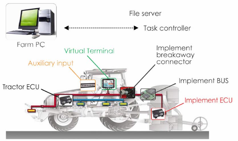
Source: http://www.ideagri.net/isobus-standard/what-is-isobus/
Our automotive embedded software developers have designed an ISOBUS protocol stack solution with layered architecture. This pre-tested and pre-packaged ISOBUS software stack is re-usable and can be deployed readily in an off-highway vehicle application.
Following are the details of the layered architecture of this ISO 11783 complaint ISOBUS protocol stack.
ISOBUS software stack layered architecture:
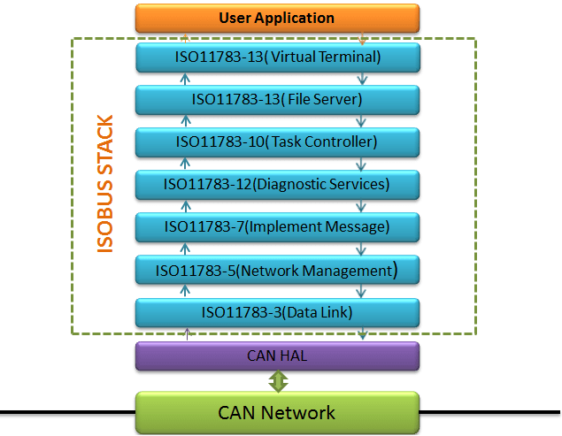
Schematic representation of ISOBUS software stack
Physical layer: The physical layer specifies the twisted and non-shielded, quad-cables with four wires. The different connectors that are used here, can be defined as:
- Bus Extension Connector: This connector provide as an extension for the implement bus and the tractor.
- Breakaway Connector: This receptacle shall be mounted at the rear of a tractor to connect the Implements to the tractor. This connector also helps the tractor ECU to connect with multiple implements.
- Diagnostic connector: This connector is used to plug diagnostic tools to the tractor.
Data link layer: This layer of the software stack supports transfer of vehicle CAN data frame with necessary synchronization, sequence control, error code and flow control.
The CAN frame can only communicate 8 byte of data so most of the PGNs (parameter group number) are of 8 byte. If the PGN is greater than 8 byte then we use defined Transport Protocols (TP layer) for transmission.
Some of the defined transfer protocols are BAM (Broadcast Announce Messaging), CMDT (Connection Mode Data Transfer), ETP (Extended Transport Protocol)
Network layer: The network layer defines services needed for communication between the Control Functions in different segments of the ISO 11783 network.
The ISO 11738 standard system has various bus segments. Interconnection between the segments is achieved by building a bride.
This could be useful to save the bandwidth. For example, in a particular application an implement may not require all the PGNs provided by the implement bus. To manage this, in network layer we can define the specific set of PGNs that a particular ECU needs for communication, thus utilizing lower bandwidth.
Network Management layer: This layer is responsible for address claim function.
The association of addresses is mandatory for the functional identification of a device (and manufacturer specifications) and the detection and reporting of network-related errors.
Each Electronic control unit is assigned a specific name of 64 bit. For the peer-to-peer communication in the network, the 64-bit name is not practical information to be exchanged between the receiver and the transmitter.
As a result, each ECU takes 8 bit address when connected to the network. The address allocation can be either static or arbitrary depending upon the developed configuration of the ECUs.
The arbitrary address allocation results in creation of different addresses each time a node is connected therefore we need a management system to store the address of each ECU.
Virtual Terminal (VT): ISOBUS virtual terminal provides the user interface for interaction with the complete system.The virtual terminal manages multiple ECUs through a common unit.
The control actions (undertaken from user end) can be customized at this layer. For instance, the user can give a specific control action from the virtual terminal to the implement.
ISOBUS Task Controller and management information system: This is the application layer which defines the requirements and services needed for communicating between the task controller (TC) and electronic control units.
Tasks are the necessary data for all kind of field operations that the tractor and its implements act upon.
The task controller layer handles the control inputs from the user through the VT. It is the responsibility of the task controller to store all the data from a farm management system in order to control one or more tasks.
For example, a particular instruction is given through the VT to the field implement. This is communicated through the task controller, via the data link layer to a particular implement ECU.
ISOBUS Diagnostic layer: The ISOBUS software stack solution supports a data driven diagnostic test system. A dedicated tool is being installed by the user to get all the vehicle specific data.
There are defined error codes for diagnosed technical issue or breakdown. Each error code is specified by ISO standard in the form of a PGN or SPN used for the diagnosis purpose.
It helps the technician to easily diagnose the real cause of technical breakdown. The diagnostic messages produced also helps in recognition and fixing of the bug.
File server: The file server prototype facilitates the transmission and exchange of large multimedia file and image data files in the ISOBUS architecture.
When we talk about the agricultural automotive, there are versatile data types that needs to be processed. It is not limited just to text data which is comparatively of minimal size and can be transmitted via the data links layers efficiently.
Suppose, the system needs to process the large size image data of a field plot that needs to be harvested.
This kind of data needs a file server system to collect the data from the camera implement. It is then processed and sent to the corresponding ECUs and further to the end system User Interface (UI) or GUI.
Implement Messages Application layer:
The message set specified by this part of ISO 11783 is designed to support the transfer of data from tractor ECU to an implement for information from ECU. It enables coordination between implement and tractor.
It supports messages containing information regarding time, ground speed, distance, navigation, PTO (power take-off) parameters, three-point hitch, general process data, and lighting function parameters etc.
Some of the messages are regularly repeated at fixed intervals and others are transmitted upon request only.
