The features enabled by electronic modules in modern day vehicles have been increasing not only in number, but also in complexity.
This is primarily due to the increased focus of the global automotive industry stakeholders to deliver enhanced safety and comfortable driving experience to the end-users.
To achieve the above mentioned objectives, OEMs equip modern cars with features such as Anti-lock Braking System (ABS), power-controlled steering, power windows, turn indicators, Android Infotainment System and more.
These features are controlled and managed by Electronic Control Units (ECUs) that work independently.
All these ECUs, integrated within a vehicle, are also required to communicate with each other.
This inter-ECU communication is managed and controlled by a Body Control Module (BCM) unit.
What is the Function of Body Control Module?
Body Control Module in automotive, makes use of the vehicle’s bus system (CAN, LIN, etc.) to communicate with different ECUs in the vehicle.
This module can be considered to be the brain controlling different body parts (different ECUs) by sending and receiving signals through the nerves (vehicle BUS).
A BCM unit, which is also an ECU, acts as a gateway or hub in order to interact with different ECUs. This mitigates the need for cabled plug-in connection between ECUs within the vehicle.
Hardware & Software Components of Body Control Module Architecture
A typical Body Control Module ECU consists of a microprocessor to control the various functions of vehicle’s body electronics (power window, wiper, side-view mirrors and more).
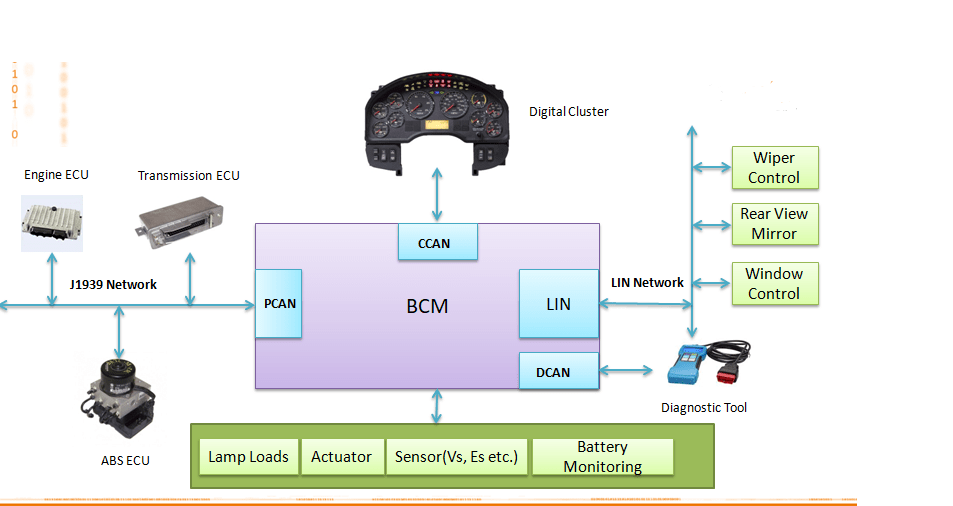
Additionally, there are ports provided on the BCM platform for the purpose of communication with different ECUs, instrument cluster, sensors, actuators, etc.
Various other components can also be integrated to the BCM unit depending on the specific requirements and automotive use-cases.
The devices or hardware that connect to a Body Control Module ECU can be categorised into input and output devices:
- Input Devices: Devices that feed data to the body control module and include sensors (potentiometers, variable resistors, magnetic pickup, etc.)
- Output Devices: Devices that are tasked with generating a response to the signal received from the input devices (relays and solenoids are typical examples of output devices in the context of BCM)
We will talk about these in detail as we proceed.
Apart from the hardware components, the BCM unit may also require to be integrated with different automotive stacks based on standards like J1939, Unified Diagnostic Services (UDS), OBD2, ISOBUS and more.
APIs to enable the communication with the application layer are usually integrated with the BCM.

The above Body Control Module block diagram indicates how the unit is connected to various input and output devices and the communication flow between these components.
How Does a BCM Control Unit Work?
Automotive Body Control Module is a multi-faceted electronic component that supports multiple functions, the foremost being the management of a gamut of automotive body electronics.
The body control module receives data from the input devices and controls the output devices based on this data.
For instance, when the user presses the power window switch, the car’s battery sends power to the BCM unit, to communicate with the ignition module. This, in turn, sends a signal to the load that will rotate the motor and control the window.
Likewise, there are innumerable body control functions that need to be performed smoothly and reliably. Controlling these parts would also be possible without a BCM unit; but that would amount to additional wiring inside the vehicle.
A body control module eliminates the need for this additional wiring. It also manages the flow of power so that the electrical module of the car does not get over-burdened when multiple functions are carried out at the same time.
Partner with Us for State-of-the-Art Body Control Module Solutions
Backed by 11+ years of experience in automotive embedded solution, at Embitel Technologies, we offer an array of Body Control Module (BCM) solutions and related services.
Enlisted and elaborated here are some of the key-features of our BCM reference design.
- Component Level Diagnostics for All Inputs and Outputs: The ready-to-deploy body control module features component level diagnosis of all inputs and outputs that are received and relayed from the module. Component level diagnosis refers to confirming the integrity of all the sub-components and separate boards.
- Prognostics (Service-related Info): The health of the ECUs and modules are constantly monitored and timely predictions of faults are ensured. This feature is related to vehicle service.
- Front and Rear Lamp Load Control: The BCM communicates with the electric system of the vehicle by controlling the load drivers. These drivers then activate the relay and control the lamps.
- Motor Control, Actuator Control and Solenoid Valve Control: The Body Control Module developed by Embitel efficiently controls the motors, actuators and the solenoid valves. All of these are the output devices connected to the BCM.
- Rear View Mirror, Wiper and Window Control via LIN Subnet: In order to support all kinds of vehicle bus system, our BCM comes equipped with LIN subnet which can control wipers, windows, rear-view mirrors, side view mirrors, petrol lids and more.
The application layer is on top of the BCM. This layer has been developed based on MATLAB Simulink Model. The application layer has some algorithms that are needed for different purposes, depending on the use-case.
For instance, when a user tries to open the vehicle using a remote key, the radio receiver in the car receives the signal and sends it to the BCM in an encrypted form. The algorithm implemented in the application layer of the body control module processes this signal and initiates the mechanical actions to open the door.
Some of the algorithms implemented in the application layer are:
- Trip Fuel Economy: Deduces the fuel used by the car in a trip.
- Trip meter: Computes the distance covered during the trip as set by the user.
- Fuel Level: Takes the data from the fuel tank sensors and calculates the fuel left in the tank.
- Odometer: Shows the total distance covered by the vehicle.
- Distance to Empty: Computes the distance the vehicle can cover with the available fuel in the tank.
- Gear Advisory system: Decides the most appropriate gear to drive based on the current speed, and displays this information to the driver.
Additional algorithms can be implemented based on specific requirements.


