
Tools and Technologies
Development & Validation Tools:
Vector CANoe
- Used for simulation and command validation
- Enabled realistic system behaviour testing
Tessy
- Ensured structured unit testing
Polyspace
- Enforced MISRA compliance at module and integration level
Vector ODX Toolchain
- Enabled creation of compliant diagnostic deliverables
Standards & Processes:
- ASPICE (process compliance)
- Volkswagen KGAS
- MISRA C
About the Customer
The customer is a Tier-1 automotive supplier specializing in lighting systems for premium OEM platforms. They have strong expertise in projection optics, FPGA, and hardware design.
While their hardware capability was mature, the program required automotive-grade software expertise. With Embitel’s extensive experience in automotive lighting solutions, we were the right technology partner for this project.
Business Challenge
This solution, designed primarily for a high-end OEM, required alignment between hardware capability and automotive software expertise.
The challenge started from requirement analysis phase and extended into development and validation phases of the lighting solution.
- Requirement Analysis Challenges– The requirements were not available as a single, structured input. They were distributed across OEM documents and standards.
For example- Scenario definitions were not always consistent. Transitions such as display timing and fade behaviour were not clearly aligned.
This made interpretation and consolidation necessary before development could begin.
- Gap Between Hardware Expertise and Software Expectations: The customer had strong expertise in projection systems. They also had deep capability in FPGA-based design. However, the ECU had to operate as part of a vehicle network.
This introduced new expectations beyond hardware functionality. The system had to support LIN-based communication. It also needed diagnostics and flashing capability. Compliance with automotive processes like ASPICE and KGAS, a Volkswagen Standard was also required.
Embitel's Solution
Our automotive lighting team along with ASPICE experts and validation team supported the customer across the full software lifecycle of the automotive lighting ECU.
The engagement covered requirement analysis, software architecture, application development, flash bootloader, diagnostics, integration, and validation. The hardware and FPGA projection design remained with the customer.
Embitel owned the automotive software development required to make the ECU ready for OEM integration.
Making Sense of the System Before Building It
Requirement analysis and reconstruction was one of the most crucial parts of this project.
- Requirements were reconstructed from OEM documents and standards
- Relevant ECU-level behaviours were extracted from broader vehicle scenarios
- LIN command responsibilities were clearly separated from master-controlled logic
This was important because vehicle-level scenarios such as welcome, goodbye, door-open timeout, locking, unlocking, and fade-out behaviour were handled by the master. The projection ECU had to respond to LIN commands.
Each command had to trigger the correct image or video from FPGA flash memory.
Software Architecture Design
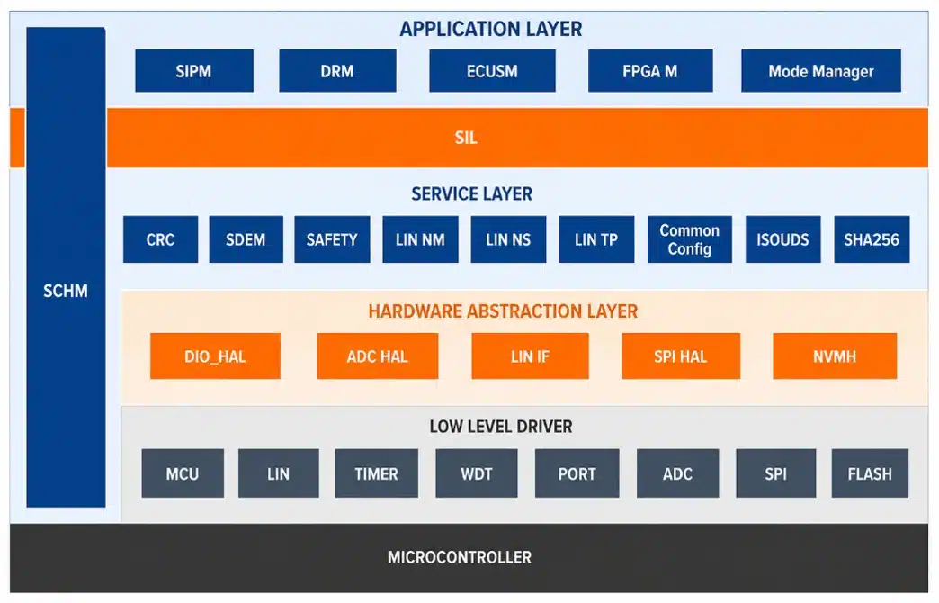
With clarity on requirements, a layered architecture was defined. The project was non- AUTOSAR-based, but we followed a similar approach.
Application logic, communication layers, bootloader, and diagnostics were separated. This ensured that changes in one area did not affect others. It also allowed configurable option for few parameters. The architecture provided a stable foundation for further development.
LIN Communication and Network Integration
The ECU was designed to operate as a LIN slave within the BCM-controlled network. This required precise handling of commands received from the master.
Each LIN command was mapped to a defined system action. These actions included selecting and triggering specific images or videos. The mapping ensured deterministic behaviour during vehicle operation.
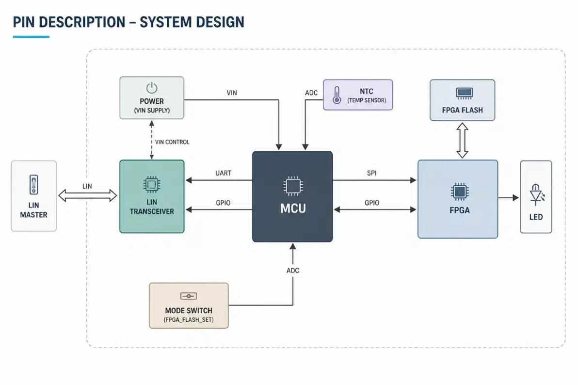
The projection system depended on coordination between MCU and FPGA. The MCU controlled the FPGA through SPI communication.
Commands received over LIN were translated into SPI instructions. These instructions triggered the FPGA to fetch and project images from flash memory. The same interface was used to send PWM values for brightness control.
This ensured a reliable link between system logic and physical projection output.
Application Development and State Management
The core application was developed to control projection behaviour based on incoming commands. This included image selection, triggering projection, and handling transitions.
- Thermal De-Rating Mechanism
- Bootloader and Flashing Mechanism
- Flash Data Security and Integrity Validation
- Diagnostics Implementation
- ODX-Based Deliverables
- Configuration and Variant Support
- Mode Management for Development Support
- End-of-Line (EOL) Support
- Verification, Validation and System Feedback
The projection LEDs generated heat during operation. This required active control to prevent overheating.
A closed-loop thermal management mechanism was implemented. The ECU continuously monitored temperature and adjusted brightness using PWM control. When temperature increased, brightness was reduced. When temperature returned to normal, brightness was restored.
This allowed the system to maintain performance while operating within safe limits.
A diagnostic-based bootloader was developed to support application flashing. The bootloader controlled the flashing sequence and validated the software before execution. This ensured that only correct and verified software was allowed to run on the ECU.
Security-related checks were implemented as part of the flashing process. Flash Data Security and integrity validation mechanisms were included.
These checks ensured that the programmed data was correct and had not been corrupted or intruded during transfer.
Diagnostics were implemented based on Volkswagen standards and KGAS requirements. Relevant services were identified and developed for this ECU.
The system supported diagnostic communication, ECU information access, and flashing-related services. Deliverables were aligned with OEM expectations to ensure compatibility with their workflows.
The OEM required outputs in ODX format. The team used OEM-provided tools to generate these files. The ODX files included both binary data and diagnostic information. This allowed the OEM to use their existing tools for flashing and validation.
Flexibility was built into the system through configurable parameters. These included fade timing, PWM thresholds, memory addresses, and fault timing. The same software supported both left and right ECUs. Variant handling was achieved through configuration without modifying the core logic.
A mode management feature was implemented to support customer-side development. This allowed switching between normal operation and direct FPGA access.
In this mode, external tools could control projection directly. This helped the customer validate projection behaviour independently.
EOL support was implemented using diagnostic-triggered projection patterns such as black, white, and check board patterns. These patterns were used to verify image quality during production testing.
V&V was carried out at multiple levels. Unit testing and MISRA checks ensured code quality. Integration testing validated communication and control flows. During system-level validation, additional issues were identified.
These included transition inconsistencies and multi-ECU behaviour. The observations were shared with the customer. This led to improvements in system behaviour and refinement of requirements.
Embitel's Impact
The engagement enabled the customer to deliver a production-ready, OEM-aligned projection ECU with measurable improvements across development, validation, and system reliability. Embitel LIN IP Stack, Bootloader expertise expedited development.
- 20–25% faster OEM integration with LIN, diagnostics, and ODX alignment. All functionality worked at once as expected. There were no changes in expected behaviour during testing at Customer Tier-1 and OEM test setup due to clearly defined requirements, design and software development and test coverage.
- 30–40% reduction in diagnostic testing effort via automation
- Improved validation coverage with extensive test scenarios
- Reduced defects through early system-level validation and scenario testing
- ~20% lower variant effort with single software baseline
- Improved reliability via thermal de-rating mechanism
- Reduced development time by 30% with our proprietary LIN & UDS stacks, Flash Bootloader and Signature Algorithm.
Outcome: Faster delivery, higher validation confidence, and a production-ready ECU aligned with OEM standards.
