As an Automotive Software or Hardware Engineer, in this era of Cars with Connectivity, in-vehicle infotainment, Smart Features, you already have a first-hand experience of what drives an automobile (beyond the engine and the four wheels).
As automotive enthusiasts and one of the stakeholders of this industry, we all have interacted with the complex network of Electronic Control Units (ECU), that makes the modern-day vehicles, a powerhouse of smart features.
Automotive ECU is the component, designed by burning millions of lines of software codes into a hardware platform, that supports features to make the vehicle more fuel-efficient, smart, and functionally safe for the drivers and passengers.
A gamut of such automotive control units, such as ABS (Anti-braking System), Telematics, Transmission Control, Battery management systems and more, work in tandem to give end-users a great driving experience.
This communication is made possible by a robust in-vehicle networking.
Such coherent coordination between the various Automotive ECUs’ is made possible by the software modules that ensure a seamless inter-ECU communication.
And that brings us to the ISO 11898 based CAN protocol and everything associated with it. Sit tight as we explore the CAN protocol and CAN Software along with its layered technology architecture.
But first, let’s start with why a need was felt for an ECU communication protocol.
Why Automotive Industry needs a CAN Software Stack?
The various control units in an automotive, are part of a closed loop network, designed inside a car. In this system or network, it is imperative for all the ECUs’ to communicate with each other and take necessary actions.
For instance, a spark from the ignition system fires up the combustion chamber. For optimum power and fuel-efficiency, the time at which the ignition is initiated, by this closed loop system, is very critical.
To achieve this, the ignition system communicates with the engine control unit with the help of in-vehicle networking. This is how exact time of ignition initiation is calculated.
A more complex system that showcases the importance of communication between the control units is Transmission Control Module, in automatic cars.
The Transmission Control Unit changes the gear ratio with the changing speed. To ensure smooth gear shifts, information from Engine Control Unit and various other nodes are collected and processed.
While the need of communication is well established now. But to develop a deeper perspective, let’s take a stroll down the lanes of the history.
In the early 70’s when electronics system had surpassed the nascent stage of development, it started leaving an impact on the automotive industry as well.
The electronic devices inside a vehicle rose in number and their correlation also got complex. The different control units had communication signals to send to each other and point-to-point wiring was making the system clogged and hard to manage.
Moreover, the information exchange between the automotive ECUs had to be in real-time. All this led to the release of CAN bus system in 1986.
CAN Bus with attributes like faster data transfer, low cost, error diagnosis and more, was the ideal bus system that the control units required. The limitations of adding new features to the vehicle that emanated from complex dedicated wiring was mitigated by CAN protocol. See also this intro to CAN bus.
Delving Deeper into CAN Protocol Stack and its Layered Architecture
CAN protocol (as defined by ISO11898), is a well-defined framework, based on which all the Automotive OEMS’s and Suppliers design communication interface between the various control units. .
CAN Protocol defines, how the vehicle data like engine speed, vehicle speed, diagnostics information etc. should be shared between the ECUs.
Every control unit (known as a node of the network) that needs to communicate using CAN protocol is connected via a Serial BUS.
To enable the transmission and receiving of the data, there are certain hardware and software components embedded in these nodes.
Typically, for a CAN node to be able to transmit and receive messages, it needs to have following components:
- Host Controller (MCU): Host controller is the Microcontroller Unit, which is integrated in the system in order to manage the execution of the functions and features of a specific Automotive Control Unit/ECU. For example, a Battery Management System (A control unit) is integrated to manage a specific task of monitoring the health of the battery in an Electric Vehicle. A Battery Management System (BMS) Microcontroller can request for information from other ECUs and sensors (via CAN), in order to handle this assigned responsibility.
- CAN Controller and CAN Transceiver: CAN controller is a hardware chip/platform that can be added to the host controller as a separate component or can be embedded inside it. This CAN Controller has the responsibility to convert the messages in accordance with the CAN protocol.
The transceiver then transmits the messages over the CAN network. The CAN transceiver along with some other layers such as ISOTP and Bootloader, together comprise of a CAN Stack.
Understanding CAN Protocol Stack Architecture
CAN protocol is based on the famous ISO- OSI reference model. There are seven layers through which every data packet passes, before it is transmitted or received.
This 7-layered structure is industry-accepted and widely adopted approach used in communication protocols.
The CAN protocol leverages two such lower layers; viz. the Physical and the Data link Layer.
When this protocol is packaged as a stack, few more modules are integrated, in order to make it suitable for the particular microcontroller platform.
Here is a snapshot of the CAN stack architecture to help you understand it better.
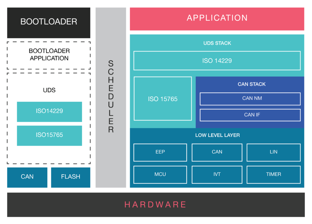
- CAN Drivers (Low Level Drivers): CAN software or CAN stack, as it is usually referred to,s has a number of low-level device drivers like MCU, EE Prom. But we will limit our discussion to CAN drivers only.The CAN driver enables the access to hardware resources, for the upper software layers.It also offers access to the hardware independent API, to the application layer.Services for initiating the transmission and callback functions of the CAN IF module are stored in the CAN driver. The CAN driver also consists of software services that manage the behavior and state of the CAN controllers (if they are part of the hardware unit).Acceptance Filtering (Hardware Based) of signals and messages is also one of the functions of the CAN Drivers.
- CAN Interface (CAN IF) Layer: CAN IF is a critical software module, that helps in the hardware abstraction of the system.It is responsible for services like Transmit Request, Controller Mode Control etc. Essentially, it carries out all hardware independent tasks, related to the flow of data to the upper layer modules of the CAN stack.In a real-world application, this layer has to be configured based on the CAN matrix file. This file contains information related to all the Tx and Rx messages.Conversion of the CAN Matrix file, which is available mostly in the DBC format, can either be carried out manually or by using a tooling solution.However, for this conversion, the DBC to Configuration File generator tool is recommended, as it completes the conversion process in a matter of few seconds. Manual method often takes 1-2 weeks depending on the size of the matrix file size.
- CAN Network Management: CAN NM, as this module is popularly known, handles the sleep/wake up functionalities. In simpler terms, it coordinates the transition from normal network operation to bus-sleep mode of the network.It also detects whether all the nodes in the CAN bus network are ready-to-sleep. In a scenario when no data units are received for a node, for certain pre-defined duration of time, CAN NM initiates the switch to BUS sleep mode. Once, the transmission of data units is restored, CAN NM wakes up the node. This helps in saving the power another resources of the system.
- Bootloader Software: Bootloader Module needs no introduction. It is a software module designed for the re-programming of an automotive ECU.The Bootloader part of the CAN stack has UDS (ISO 14229) and the ISOTP layer (ISO15765).
- ISO TP Layer (ISO15765): ISO Transport Protocol is a specialized protocol that shoulders the responsibility of the data transmission, when the data frames exceed the maximum payload of 8 bytes. ISOTP layer segments the message into multiple data frames and reassembles them in the correct order, by using the metadata.
Conclusion
CAN protocol has stood the test of time and has virtually replaced every other communication protocol used in the automotive industry.
Its robustness and data handling capabilities, has made CAN a widely used protocol in other industries including Railways, Aviation etc.
The inherent error handling capabilities also makes CAN, a protocol of choice for the majority of the automotive OEMs.
