In simple terms, Controller Area Network (CAN) can be understood as a medium that links all electronic systems in the vehicle. It is the CAN Bus that supports all the communication between different Electronic Control Units (ECU) within a vehicle.
“When CAN Bus standard was defined by BOSCH in 1980, the electronic components were a few. The payload on the network did not go beyond 8 Bytes. The data rate required for software flashing was also not very high as software still did not control a lot in the vehicles.”
Fast-forward 20 years since the introduction of the CAN Bus! We will find ourselves overwhelmed by the scale of all things software within the Automotive Industry
From the number of vehicle ECUs (control units) to the complexity of the automotive software, everything has scaled up to the newer heights.
Hence, a faster In-vehicle networking Bus standard became the need of the hour. In 2014, the enhancement to CAN was finally launched. It was called CAN FD (Flexible Data-rate). As a result, the senior avatar of CAN (remember 1980s) was awarded an honorary prefix and was rechristened (for ease of naming) as the Classical CAN.
Why the Need for CAN FD
The bandwidth requirement of the new automotive applications has been increasing more than gradually! This is mainly due to the Volume, Variety and Velocity of data from sensors and other sources being fed to the in-vehicle network of control units. Automotive ECU reprogramming is another area where large size binary files are required to be transferred over the in-vehicle network.
The bit rate and payload limitation of CAN started impeding activities like automotive ECU flashing, and faster communication for ADAS applications.
High data rate and larger payload were achieved by modifying the frame format of CAN. This new frame format (CAN FD solution) has the capability to support higher bandwidth than 1 Mbit/s and hence it could manage data payloads higher than 8 bytes.
Since the new frame format solution has the ability to support flexible data-rates (up to 8mbps) depending on the requirement of the application, it was christened as CAN Flexible Data-rate or CAN FD.
We will go into a little more details to understand how exactly CAN FD is able to fill the gap created by inherent nature of CAN operations
The data over CAN is sent in frames. The receiving nodes send an acknowledgement flag as soon as they receive the frame. As this acknowledgement is send into the transmitted frame, the sender gets an in-frame response after a successful transmission.
The transceivers present between the CAN and the vehicle ECU and the length of the physical cables often cause propagation delay. It also directly impacts the bit rate resulting in slower data transfer.
CAN FD solves this problem by using two separate frames to send the real data and the acknowledgement data. Higher bit rate is used to transmit the data itself and the nominal bit-rate is allocated to control data (acknowledgement).
We will elaborate a little more on it when we discuss the CAN and CAN FD compatibility.
The Connection between Bootloader and Controller Area Network (CAN)
In an automotive ECU, the primary function of Bootloader software is ECU Re-programming also called as ECU Flashing. The Bootloader receives the updated program through the CAN and then performs the necessary function.
There are three phases of ECU reprogramming/flashing, namely, delete, download/program and verify. In these three phases, the download time is the key factor.
In the automotive applications like ADAS, in-vehicle infotainment, CAR HUD and others, the size of the software packages is quite large. Classical CAN may take several minutes for the update or file-transfer as its max data rate is 1 Mbps.
On the contrary, with a data-rate up to 8 Mb/s supported by CAN FD ECU flashing can be accomplished in seconds. Unarguably, this is a huge advantage.
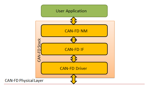
The block diagram shows the physical layer of CAN FD stack.
Classical CAN v/s CAN FD: The Striking Differences
Some of the differences which are also the main advantages are quite obvious. It includes the higher bit rate and support for larger payload. We will try to bring out some more discreet yet important differences.
But let’s first discuss the more obvious ones.
- Increased data rate: From a max of 1 Mb/s to up to 8 Mb/s, the change is glaring. Increased data rate is highly beneficial in re-programming the applications like ADAS (Advanced Driver Assistance System), as large data packets are needed to be transmitted.
- Large Payloads: CAN FD supports 64 bytes of data field as compared to 8 bytes in CAN. This huge leap in payload size translates into faster and more efficient in-vehicle network communication among the vehicle ECUs. End-of-line software upgrade also becomes faster affair with CAN FD.With 64 bytes of payload supported, there is no need for the splitting of the long messages as well. This simplifies the handling of the data, thus contributing in efficient data transmission.And now let’s move on to the discreet ones:
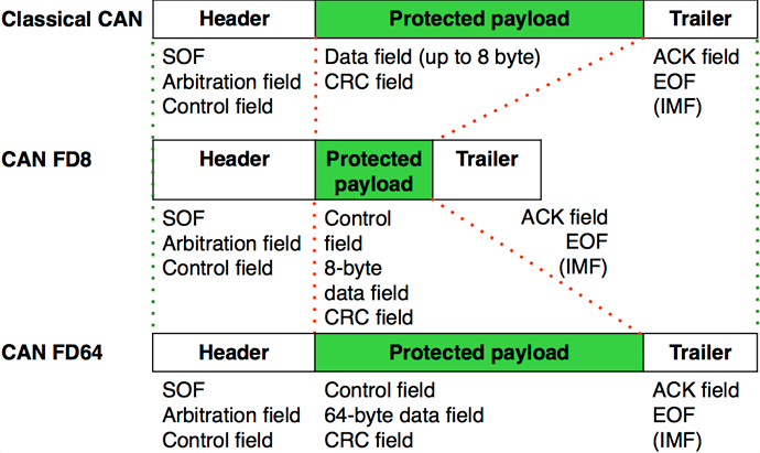
- Message Format: The message frame format has undergone some crucial changes in CAN FD bus standard. The most primary being the ability to send the control data (arbitration and acknowledgment) with a different bit rate (usually 500 Kb/s) and send the actual data at a higher bit rate.Another improvement in CAN FD is the introduction of CRC (Cyclic Redundancy Checks), that takes care of the larger frames by taking CAN Stuff bits into the account. The diagram below shows the major differences between the message frames of CAN and CAN FD.
- Data bit rate dependency: Propagation delay is quite common in CAN bus standard due to the transceivers and cable length. Propagation time is nothing but the time required to send the signal to the most distant node and get it back. The bit-rate will directly depend on the propagation delay as there is a reciprocal relation between them.There is no such dependence of bit rate on signal propagation delay. Reason being the difference in the message frame format that we discussed in the above section.
The Automotive Industry Outlook
CAN FD has been around for only 4 years and is still in the process of being adopted. The vehicles that are already in production still have classical CAN and migration is rather tricky and not very viable.
Automotive OEMs are introducing CAN FD in the new cars by adding the CAN FD transceiver to the vehicle control unit.
It does escalate the hardware cost a little but it is expected to deliver the benefits and RoI, considering the faster data transmission and ECU reprogramming that CAN FD enables.
CAN FD and Classical CAN: The Compatibility Factor
A Classical/Classicalal CAN controller will not be compatible with CAN FD, however, the vice-versa is true. Backward compatibility very much exists between CAN FD and classical CAN.
It implies that both CAN and CAN FD nodes can be used together as CAN FD is backward compatible with Classical CAN. However, special hardware would be required.
Following are some of the reasons why CAN and Can FD backward compatibility is possible:
- Dependence of data bit-rate on transmission characteristics and physical layer and not on propagation delay.
- Some of the compatibility issues can be resolved by the transceivers that feature passive partial networking and are both CAN and CAN FD tolerant.
The Conclusion
“The future bandwidth requirements are going to be higher and CAN FD seems to fit the bill. CAN FD is also perfect for communication in Electric Vehicles as they demand higher bandwidths. The communication between the vehicle control units, DC inverter ECU, battery management systems etc. in an EV definitely calls for very high data transmission and inter-ECU communication. CAN FD has a serious use case here.”
Even in gasoline and diesel powered cars, new electronic architectures are under extensive research. We could even possibly witness CAN FD subnets in Powertrain and Body Control Module along with Ethernet. Whatever the future may hold, the legacy of CAN will continue with CAN FD.
