New age Automotive ECU applications are complex systems. An insane amount of information needs to be processed in real-time and rendered to various other systems. An ADAS system, for example, uses an advanced algorithm to processes data from the cameras, radars, GPS and other sensors to assist the drivers in avoiding judgement errors while driving. Such a data-heavy system has to be fool-proof and to ensure that, the testing must be rigorous and comprehensive.
Testing such complex systems on a real vehicle to prove every possible use-case is not a viable option. It incurs huge overheads and it is very challenging to test every scenario. Moreover, performing the tests at the final assembly entails test-related changes that can seriously impact the schedule as well as the cost. Also, the entire assembled platform might not be available for testing at the required time.
Simulation happens to be the only plausible approach to such testing and thus arrives Hardware-in-Loop testing methods. Not only does it automate the testing process but also brings in the tests much early in the software development lifecycle.
While we make it sound very easy to have HIL Testing unravel the software defects without an assembled product, a lot actually goes into the process.
Let’s begin by understanding HIL Testing at a high level, followed with a detailed analysis of the HIL Test system and the testing process.
What is Hardware-in-Loop Testing?
In the simplest terms, HIL Testing is a method to validate a software in a simulated environment where ECU functions can be tested without having the actual vehicle system. HIL Testing is used to validate the communication, system integration and the functionality aspect of automotive software.
Ideally, an ECU under test receives huge number of I/O signals that represent different functionalities. A comprehensive test means that all these functionalities are tested under the scenarios based on the requirements. So, what exactly conspires during HIL tests?
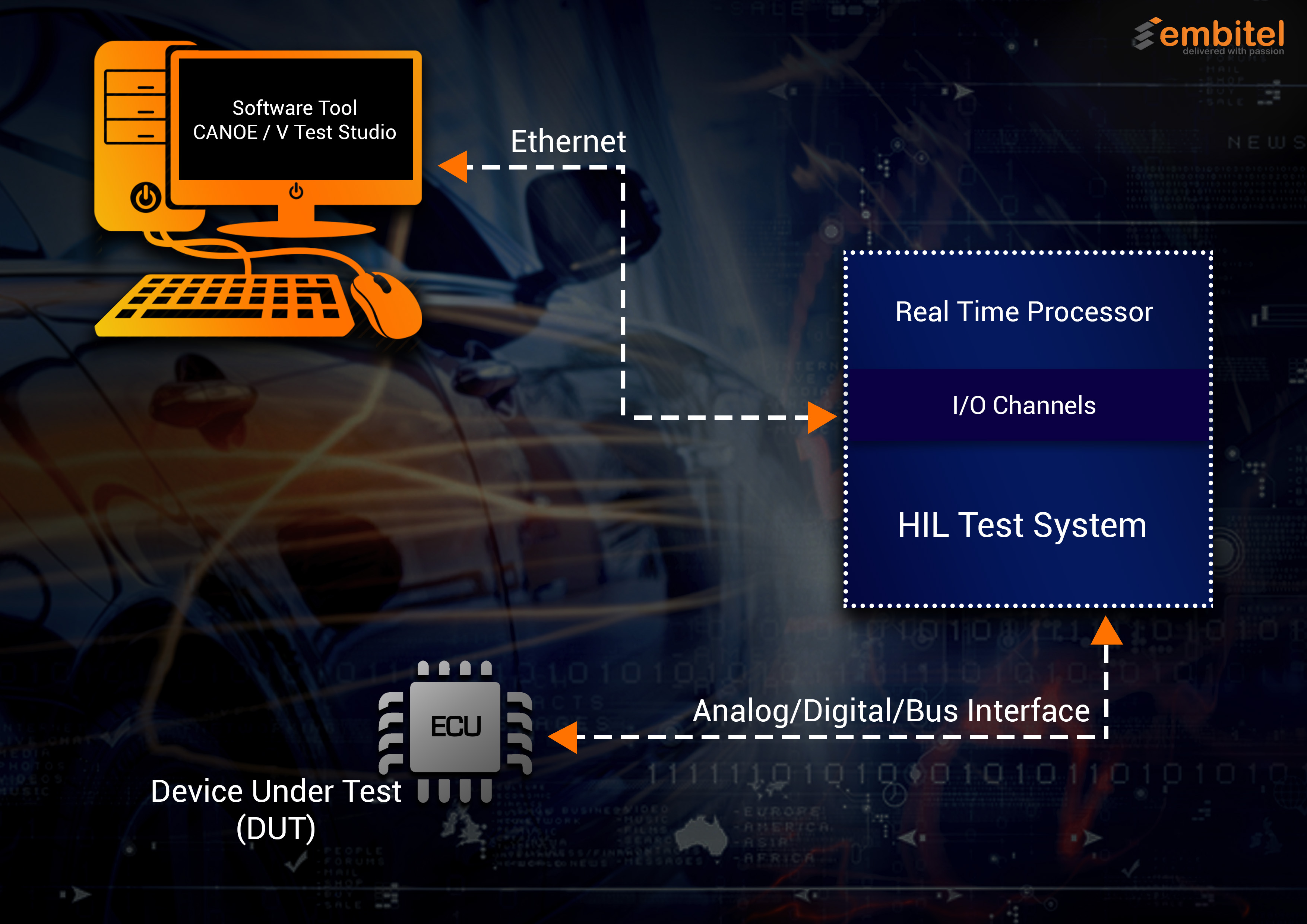
During HIL Testing, the ECU is connected to a Test System that mimics an assembled product (an engine, a body control module or even the entire vehicle system). It interacts with the input and the output of the ECU under test, as if it were an actual vehicle.
Using a HIL Testing software, different test scenarios can be created, and the output validated. Depending on the software requirements, the test coverage can be expanded without worrying about the cost and physical risk to the system.
Hardware-in-Loop Testing Architecture
Finding HIL Testing in the V-Cycle Diagram
In the software development lifecycle, HIL Testing is the step where the software validation is performed. As clear from the V-cycle diagram, it is executed against the software requirements which may comprise functional as well as safety requirements (ISO 26262 compliance development).
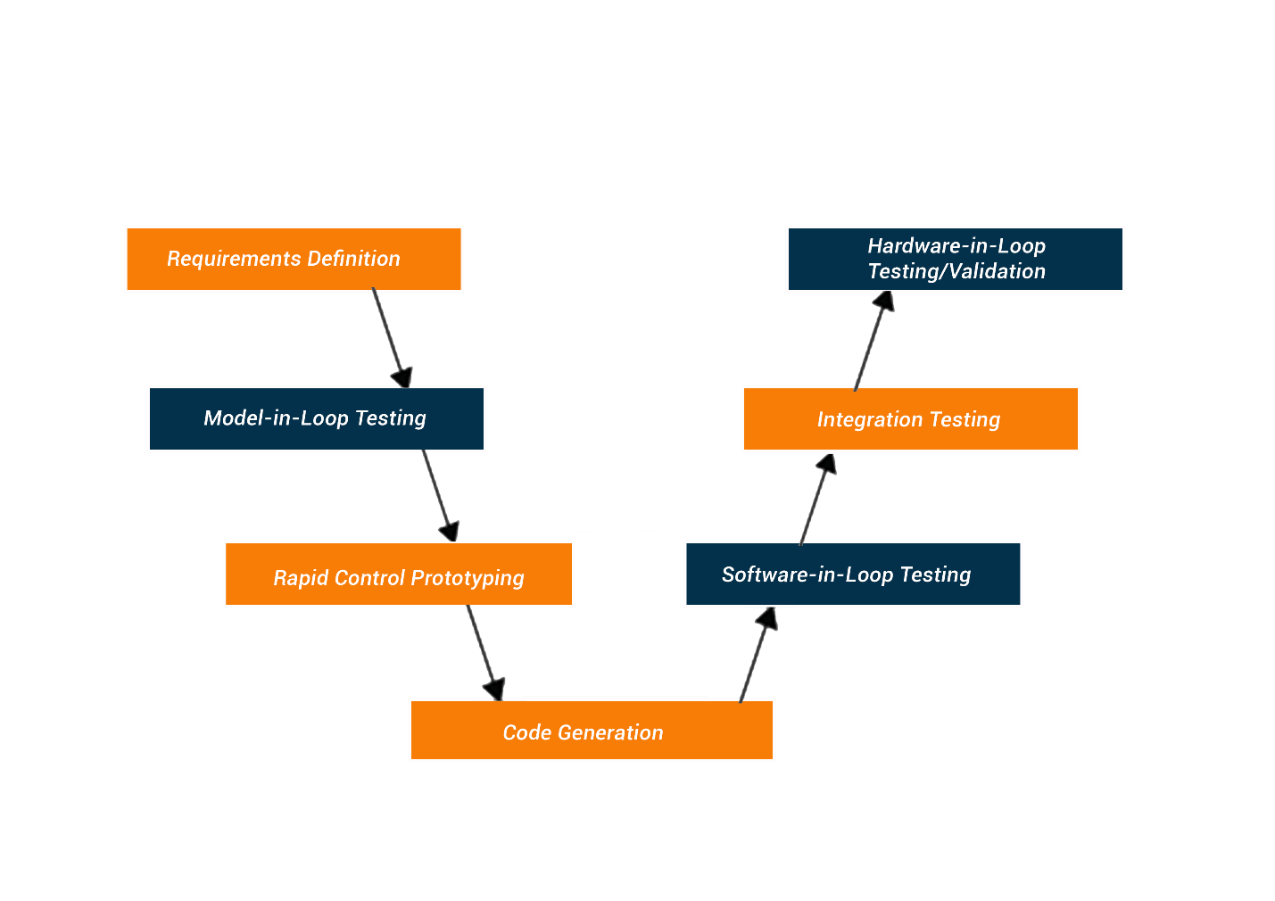
Unit testing and integration testing precede the stage where the software is ready to be validated keeping the target hardware in loop.
A model based development paradigm takes a different approach where Hardware-in-Loop testing is preceded by Processor-in-Loop (PIL Testing), Software-in-Loop (SIL Testing), and Model-in-Loop (MIL Testing).
Understanding a Typical HIL Test System
A HIL test system is at the heart of HIL testing. The simulation part of the testing that we mentioned earlier, needs an environment that can trick the ECU into believing that it is connected to a real vehicle.
The test system provides this environment. And for that purpose, it requires a gamut of software and hardware components. Let’s discuss them!
- Real-time Processing Unit: The processing unit is at the core of a HIL Test System. It performs the most intensive task of executing the components of the test system. Complex automotive controllers have a large number of I/O channels and bus communication to be handled. From logging of the data and I/O communication to test stimulus generation, it is the processing unit that keeps the tasks going.Why a real-time processor, you might ask? Well, the test system replaces actual ECUs and their I/O signals. For the test to be executed perfectly, an accurate simulation of the vehicle electronics has to be ensured. And hence, a real-time processing unit.
- I/O Interfaces: The ECU under test needs to be connected to the HIL Test system for the signals to interact. The I/O interfaces are responsible for establishing this connection. These interfaces can be digital or analog signals.Using the I/O interfaces the test engineers can:
- Generate stimulus signals
- Manage the communication of the sensors and the actuators between DUT and Test System
- Manage current/voltage and optical I/O channels
The importance of I/O interfaces also lies in the fact that it has to make sure that the DUT must always behave in a way that it is controlling the actual hardware. Test System providers may provide both dedicated as well as configurable I/O interfaces.
- Software Interface: Software components are essential to the HIL Test System as these are required for writing test cases, creating required stimulations and generating test reports.Typical software components that aid the HIL Test system are:
- Test Case Scripting: The tool is required to create test cases using scripting language. Various scripting languages are used depending on the HIL Test system brand. For example, Vector VT System uses VTest Studio for writing test cases in CAPL script. On the other hand, DSpace uses Python for the same.
- ECU simulation: A software tool for simulating other ECUs in a vehicle is of the prime importance in an automotive HIL testing setup. The ECU under test might have to interact with other ECUs during its operation. And therefore, during the HIL testing all such ECUs need to be simulated.
- Device Under Test (DUT): Device under test (DUT) is the control unit, the functionality of which is being validated. It can be a powertrain ECU, a Battery Management System ECU or any other automotive control unit. For testing purpose, DUT is connected to the HIL Test System.
In addition to these, there are components that manage power supply by simulating the battery and other auxiliary modules like load boards.
Widely Used HIL Test Systems in Automotive Application Development
Several vendors have their HIL Test Systems out in the market. In the context of architecture, application framework and concept, most HIL test systems are almost identical. The only difference that one can spot is that they cater to diverse industries. For instance, VT System from Vector is designed specifically for automotive application development. DSpace caters to power electronics industry as a whole.
We will now discuss some of the popular HIL Test Systems that are deployed in Hardware-in-Loop testing.
- Vector VT system: VT System is a popular modular test system that is designed to access the ECU’s inputs and outputs for validation. The system works together with tools like CANoe and VTest Studio. Based on CAN Bus protocol, VT System also supports CAN, LIN and other communication protocols.
- National Instrument Lab View: Lab View from NI, is a HIL test framework that helps the engineers create flexible test applications using a graphical programming approach. A test system designed to integrate a vast range of hardware, LabVIEW serves diverse industries to develop smart machines and industrial equipment.
- DSpace System: The Test System comprises the complete tool-chain (software and hardware) required for a simulated test environment. The biggest advantage of using DSpace for automotive software development is that it is designed to support the tests methods and coverages mandated by ISO 26262 standard.
HIL Testing in Action: Testing a Motor Control System
Motor Controller ECU has some highly safety-critical tasks at hand viz. power steering, EV powertrain and so on. State-of-the art HIL Testing, thus becomes mandatory.
Generally, the motor controller ECUs need to be tested for
- PWM measurements
- Checking whether Encoders and resolvers are working fine at higher clock rate
- Evaluating the functioning of the Position sensor
A HIL Test system simulates the power electronics, electric motor and the vehicle environment at the signal, electrical and mechanical levels.
And for this, the HIL Test system needs access to
- ECU connections in order to control them
- Power supply
- Communication Bus (CAN)
- I/O channels
The HIL Test System does the following tasks:
- Simulates other ECUs with the help of CANoe or equivalent tool (depending on the type of HIL Test system deployed)
- Generates the required sensor input such as PWM signals, required voltage
- Simulates the actuator (electric motor) with electronic load and measures the output from the motor controller ECU such as PWM duty cycle
- Measures the voltage and current supplied
The Test Cases are written in software tools such as VTest Studio using scripts (CAPL, Python). The test reports are generated after the required tests are executed.
What are the Challenges Faced in HIL Testing of an Automotive System
HIL (Hardware-in-the-Loop) testing is a crucial aspect of automotive system development, but it comes with its fair share of challenges. Here are some of the key challenges faced in HIL testing of automotive systems:
- Hardware and Software Integration: Integrating a motor controller with other vehicle systems and components poses challenges in terms of seamless integration and compatibility. Tools like dSPACE SCALEXIO or VT system from Vector can be utilized for hardware integration and testing, ensuring proper communication between the motor controller, sensors (e.g., position sensors), actuators (e.g., electric motor), and communication networks (e.g., CAN bus).
- Realistic Simulation: Simulating the dynamic behaviour of the electric motor requires accurate and realistic simulations. MATLAB/Simulink coupled with Simscape Power Systems enables engineers to create high-fidelity simulations considering motor control algorithms, motor parameters, and environmental factors like temperature and load variations. These simulations replicate real-world motor characteristics and dynamic responses.
- Model Complexity: Automotive Motor Controllers involve complex mathematical models for motor control algorithms, feedback control loops, and safety mechanisms. Handling the complexity of these models while maintaining real-time performance necessitates powerful hardware-in-the-loop simulation platforms like dSPACE SCALEXIO or NI VeriStand, capable of executing high-fidelity motor control models with low latency.
- Timing and Synchronization: Achieving precise timing and synchronization among the Motor Controller, sensors (e.g., position sensors), actuators (e.g., electric motor), and simulation models is crucial for accurate testing.
- Data Acquisition and Signal Conditioning: Capturing and processing data from various sensors, such as position sensors, current sensors, and temperature sensors, requires reliable data acquisition systems. Systems like NI CompactDAQ or dSPACE DS4301 enable engineers to acquire and condition sensor signals with high accuracy and low latency, providing reliable feedback for testing and validation.
- Test Case Design and Coverage: Designing comprehensive test cases involves covering various operating conditions, motor control strategies, and fault scenarios. Model-based testing tools like MATLAB/Simulink’s Simulink Test or dSPACE AutomationDesk facilitate the design and execution of test cases based on model specifications. These tools ensure thorough test coverage by considering different control modes, load conditions, and fault scenarios.
- Hardware Fault Emulation: Emulating realistic hardware faults or motor failure scenarios is crucial to evaluate the Motor Controller’s fault detection and response mechanisms. There are tools available that enable engineers to inject faults, such as sensor malfunctions or actuator failures, into the HIL test setup. This allows for simulating realistic fault conditions and validating the Motor Controller’s ability to handle faults and ensure safe operation.
- Cost and Resource Constraints: Setting up an effective HIL testing environment involves managing cost and resource constraints. This includes acquiring specialized hardware, software licenses, and skilled personnel. Organizations must carefully allocate resources, including HIL simulation platforms, data acquisition systems, and fault emulation units, to meet testing requirements within budget limitations.
Conclusion
Hardware-in-Loop testing gives the automotive industry a chance to test their solutions before the actual target platform is ready. Not only does this ensure reduced time-to-market but also leads to a better and more technically matured product.
The probability of call-backs is reduced significantly when you have a thoroughly tested product in hand. Thanks to some great HIL Test Systems, automated HIL Testing is redefining the automotive industry and the future only looks brighter.
